
Time Delay Wiring Diagram
Off delay timer relay wiring diagram. Not merely will it help you attain your desired results quicker, but also make the complete procedure less difficult for everybody.

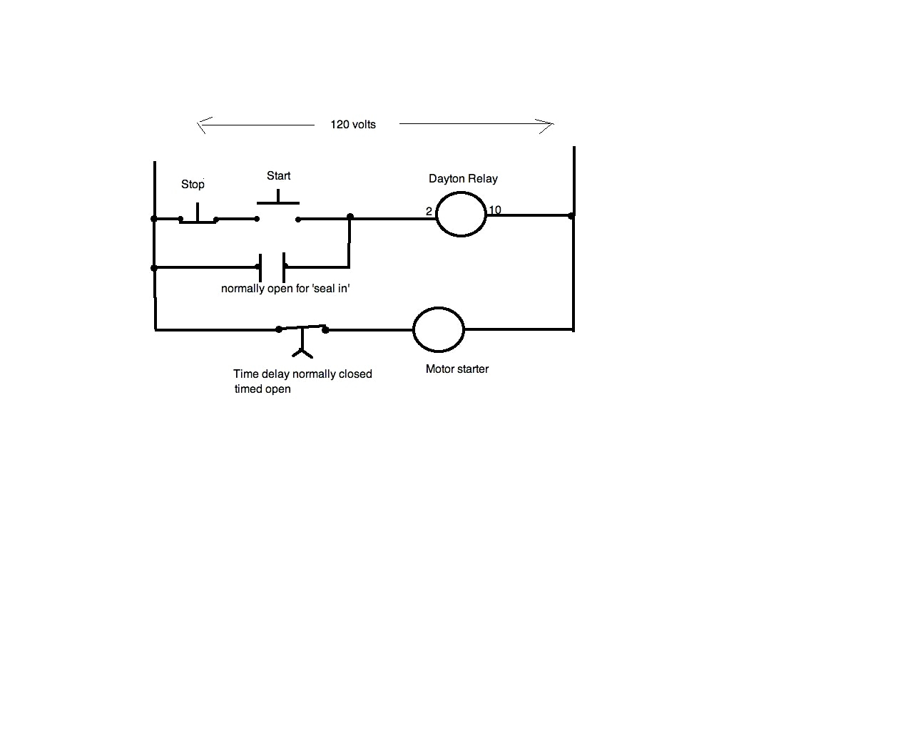
Dayton Time Delay Relay Wiring Diagram Gallery
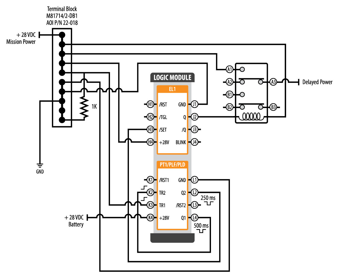
Module load at pin 2.

Time delay wiring diagram. Wiring diagrams for a ceiling fan and light kit do it yourself help com. With such an illustrative guide, you'll be capable of troubleshoot, stop, and complete your tasks easily. At the end of the time delay (t1), the output is energized.
Note that the user must provide the voltage to power the load being switched by the output contacts of the time delay relay. Hager ezn002 delay off timer. Find instant quality info now.
By iot | december 11, 2021. For dc products, pay attention to wiring according to the circuit diagram and pay attention to the polarity of the power supply. Madcomics timer switch wiring diagram hager surface mount 24hr analog eh 010 instruction manual pdf to connect 225 eh711 24hrs time contactor digital eg103b e welcome electronic lighting i need it is wall.
The fan can be suitable for ceiling fixing. On delay timer circuit diagram wiring diagram contactor with push button circuit diagram of delay timer on off power off delay timer circuit diagram 2 way lighting circuit triggering transformer push button fan switch light activated switch circuit diagram wd081 text. It shows the components of the circuit as simplified shapes, and the power and signal friends in the middle of the devices.
Hager timer switch wiring diagram. View is from the flat side with the catalog numbers. Get results from multiple engines.
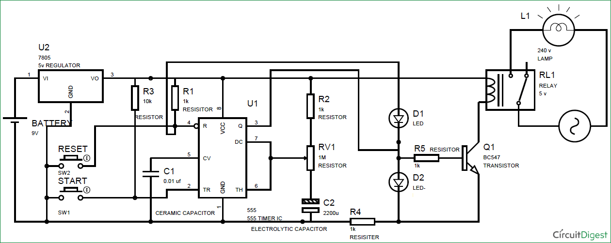
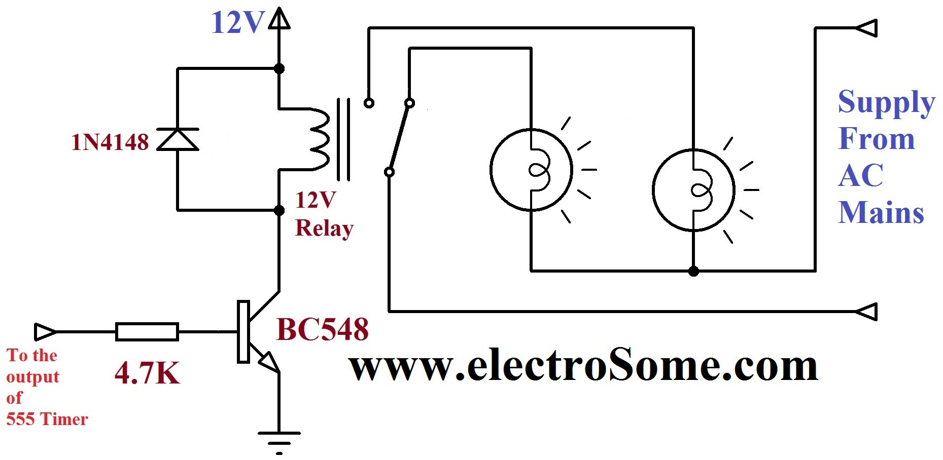
The wiring diagram below shows the wiring setup you need to connect your new timed fan to your existing light circuit ceiling rose so that when the ligh is turned on so is the fan. Every time delay relay has an internal relay (usually mechanical) with contacts that open & close to control the load. Before going into detail of time delay circuit, first we need to learn about 555 timer ic first.
I have a bionaire brand table electric fan. On delay relay contacts wiring. Below you can find the pin diagram of 555 timer ic along with the details of each pin.
Solid state timer relay electrical academia using time delay relays to cycle a traffic signal 555 ic motor control systems part c electromechanical worksheet digital circuits how wire an off dol starter overrun the for 5 minutes quora circuit before turn on working. They are represented by the dotted lines in the wiring diagrams. Trigger pin is dragged from the negative input of comparator two.
When the trigger is applied, the time delay (t1) begins. 35 latest hager 4 pole contactor wiring diagram stephan fuchs. Each component should be placed and linked to other parts in particular manner.
When the trigger is removed, the output remains energized for the time delay (t2). Off delay timer relay wiring diagram. Zero delay usb encoder wiring diagram.
Voltage, the time delay relay is ready to accept a trigger. Time delay is variable and dependent on the resistance value of rt. The kh1 series adjustable on delay module connection diagram.
This post is about the staircase timer wiring diagram in the diagram i use the on delay timer finder 8 pin relay re electrical circuit diagram timer diagram. This pin should be connected to ground. Rt @ 0 ohm = minimum delay, rt @ 1m ohm = maximum delay.
If the repeated use interval is less than the preset. Zero delay board arcade usb encoder to pc raspberry pi zippy joystick control sanwa american push button connection cable arcade usb encoder pc zero delay arcadezippy joystick aliexpress. 5) after the time relay is out of working state, it should be reset immediately for the next use.
This is just one of the solutions for you to be successful. Time delay switch wiring diagram 555 time delay circuit diagram tradeoficcom wiring diagrams second. So youve just received your zero delay arcade usb encoder and its time to wire it up.
For products using a power trigger to initiate the The comparator two output is connected to set pin.
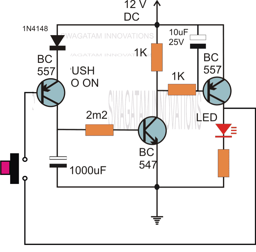
Simple Delay Timer Circuits Explained Homemade Circuit Projects
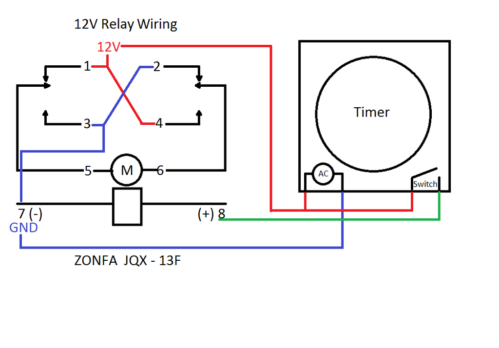
12V Time Delay Relay Wiring Diagram Collection

How to Build a Simple Industrial Delay Timer Circuits

Dayton Time Delay Relay Wiring Diagram A652

Time Delay Switch Wiring Diagram Timer, Circuit diagram, Electrical panel

Simple Delay Timer Circuits Explained

Dayton Time Delay Relay Wiring Diagram Free Wiring Diagram
Time Delay Relay Replacement
Simple Time Delay Circuit using 555 Timer ArRoboticsBlog

Simple Delay Timer Circuits Explained

Time Delay Circuit Using 555 Timer
Dayton Time Delay Relay Wiring Diagram A652

Dayton Time Delay Relay Wiring Diagram Gallery

Get Dayton Time Delay Relay Wiring Diagram Download
60 Best Of Time Delay Relay Wiring Diagram

ICS Time Delay Module Applications and Wiring

Dayton Time Delay Relay Wiring Diagram Gallery
20 Elegant Time Delay Relay Wiring Diagram
Dayton Off Delay Timer Wiring Diagram Collection